
Aug 14, 2026pneumatic fittings

How to Choose the Correct Tube Size for Pneumatic Fittings

Air supply → FRL → solenoid valve → fitting → tube → flow controller
83e82658-8bfc-4390-aa06-14806a4fffe8

How to Choose the Correct Tube Size for Pneumatic Fittings

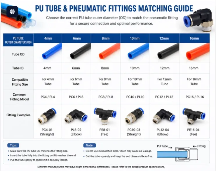
Choosing the correct tube size for pneumatic fittings is an important part of designing an efficient and reliable compressed air system. A tube that is too small can restrict airflow and cause pressure loss, while an unnecessarily large tube may increase cost and take up more installation space.
For automation equipment, packaging machines, assembly lines, and other pneumatic systems, tube size should be selected according to airflow requirements, working pressure, tubing length, cylinder size, fitting size, and operating speed.
This guide explains how to choose the correct pneumatic tube size and avoid some of the most common selection mistakes.
1. Understanding Pneumatic Tube Sizes
Pneumatic tubing is normally specified by its outside diameter (OD).
Common metric tube sizes include:
Tube Outside Diameter
Typical Application
4 mm
Small pneumatic devices and compact equipment
6 mm
Small cylinders and general automation
8 mm
Medium-size cylinders and machinery
10 mm
Higher airflow pneumatic systems
12 mm
Large cylinders and industrial equipment
14 mm
High-flow applications
16 mm
Large pneumatic systems and main air lines
For example, a pneumatic fitting marked PC8-02 commonly indicates a straight push-in fitting designed for an 8 mm OD tube, with the other part of the code referring to the threaded connection according to the manufacturer's coding system.
Always check the supplier's dimensional specifications because model codes and thread designations can vary.
2. Why Pneumatic Tube Size Matters
Tube diameter directly affects how easily compressed air can move through a pneumatic system.
If the tube is too small, the system may experience:
  • Excessive pressure drop
  • Restricted airflow
  • Slow cylinder movement
  • Longer machine cycle times
  • Reduced cylinder performance
  • Higher energy consumption
A larger tube provides more flow capacity, but bigger is not always better.
Oversized tubing can:
  • Increase material cost
  • Require larger fittings
  • Occupy more installation space
  • Increase the volume of compressed air that must be filled and exhausted
The goal is therefore not to choose the largest tube possible, but to select the smallest practical tube that can provide the required airflow with acceptable pressure loss.
3. Match the Tube Size to the Pneumatic Fitting
One of the first things to check is whether the tube outside diameter matches the fitting.
For push-in pneumatic fittings, the tube is inserted directly into the release sleeve and sealing mechanism.
For example:
Fitting Tube Size
Recommended Tube OD
4 mm
4 mm
6 mm
6 mm
8 mm
8 mm
10 mm
10 mm
12 mm
12 mm
16 mm
16 mm
Never try to insert a tube with a different outside diameter into a push-in fitting.
Even a small dimensional mismatch may cause:
  • Air leakage
  • Poor tube retention
  • Seal damage
  • Tube disconnection
  • Unstable pneumatic performance
The tubing should also have suitable dimensional tolerance and surface quality for push-to-connect fittings.
4. Consider the Required Airflow
Airflow requirement is one of the most important factors when selecting pneumatic tubing.
A small pneumatic cylinder operating slowly may require relatively little compressed air.
A large cylinder operating at high speed requires considerably more airflow.
For example, compare:
Application A
  • Small cylinder
  • Short stroke
  • Low operating frequency
  • Short tubing
A 4 mm or 6 mm tube may be sufficient.
Application B
  • Large-bore cylinder
  • Long stroke
  • High operating frequency
  • Fast extension and retraction
An 8 mm, 10 mm, 12 mm, or larger tube may be necessary depending on the calculated flow requirement.
Therefore, tube diameter should not be selected based only on the cylinder's port thread.
5. Consider the Length of the Tube
Tube length is another factor that is sometimes overlooked.
As compressed air travels through tubing, friction causes pressure loss.
In general:
Longer tube + smaller diameter = greater pressure drop
For example, a 6 mm tube may perform well over a short distance between a solenoid valve and a small cylinder.
However, if compressed air needs to travel a much longer distance, increasing the tube diameter may help reduce pressure loss.
Whenever possible, locate pneumatic control valves close to the actuator.
This can:
  • Shorten tubing
  • Reduce pressure losses
  • Improve cylinder response
  • Reduce compressed air volume
  • Improve machine cycle time
6. Check the Inner Diameter, Not Only the Outer Diameter
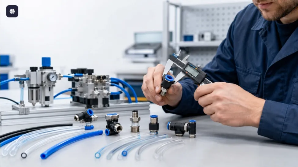
Pneumatic fittings are normally selected according to the outside diameter of the tube, but airflow depends strongly on the inside diameter.
Two tubes can have the same outside diameter but different wall thicknesses.
For example:
8 mm OD tubing
does not automatically mean that every 8 mm tube provides exactly the same internal flow area.
A thicker wall means a smaller inner diameter.
Therefore, for applications where airflow is critical, engineers should check:
  • Tube OD
  • Tube ID
  • Wall thickness
  • Maximum working pressure
  • Minimum bend radius
  • Tube material
7. Metric vs Inch Pneumatic Tubing
Another common mistake is mixing metric and inch tubing.
Common metric tubing includes:
  • 4 mm
  • 6 mm
  • 8 mm
  • 10 mm
  • 12 mm
  • 16 mm
Common inch tubing includes:
  • 1/8"
  • 1/4"
  • 5/16"
  • 3/8"
  • 1/2"
A 1/4-inch tube is approximately 6.35 mm, but it should not automatically be treated as interchangeable with a 6 mm tube.
The difference may appear small, but push-in fittings depend on precise tube dimensions for sealing and gripping.
Always use:
Metric tube → metric fitting
and
Inch tube → corresponding inch fitting
unless the fitting manufacturer specifically confirms compatibility.
8. Tube Size and Thread Size Are Different
This is particularly important when purchasing pneumatic fittings.
A pneumatic fitting has two different connection dimensions:
Tube connection
and
Thread connection
For example, a fitting might connect:
8 mm tube × 1/4" thread
The 8 mm dimension describes the tube outside diameter.
The 1/4" dimension describes the threaded port.
They should not be confused.
Pneumatic fittings may also be supplied with different thread standards, including:
  • PT
  • NPT
  • BSPT
  • BSPP / G
  • Metric threads
Before ordering, confirm both the tube OD and thread standard.
9. Do Not Select Tube Size Based Only on Thread Size
A common purchasing mistake is assuming that a certain thread size always requires a certain tube diameter.
For example, equipment with a 1/4" threaded port does not necessarily mean that an 8 mm tube must be used.
Depending on the application, fittings may be available in combinations such as:
  • 6 mm × 1/4"
  • 8 mm × 1/4"
  • 10 mm × 1/4"
The correct combination depends on the required airflow, available fitting configuration, equipment design, and manufacturer's specifications.
10. Consider Working Pressure
Tube size alone does not determine whether tubing is suitable for a pneumatic system.
The tube must also be rated for the required working pressure.
Before selecting tubing, check:
  • Normal operating pressure
  • Maximum system pressure
  • Temperature
  • Safety factor
  • Tube material
  • Manufacturer's pressure rating
Never assume that two tubes of the same outside diameter have the same pressure rating.
Wall thickness and material can significantly affect pressure capability.
11. Choose the Correct Tube Material
Tube material also affects pneumatic system performance.

PU Tubing

Polyurethane (PU) tubing is widely used in industrial automation because it is flexible and easy to route.
Typical applications include:
  • Pneumatic cylinders
  • Solenoid valves
  • Packaging machines
  • Assembly equipment
  • Robotics

Nylon Tubing

Nylon tubing generally provides good mechanical strength and is often selected for applications requiring higher pressure capability or greater rigidity.

PE Tubing

Polyethylene tubing can be suitable for certain general pneumatic applications where flexibility and cost are important.
Material selection should always consider pressure, temperature, chemicals, movement, and environmental conditions.
12. A Practical Pneumatic Tube Selection Example
Suppose an automation machine uses:
  • 50 mm bore pneumatic cylinder
  • 200 mm stroke
  • 0.6 MPa operating pressure
  • Moderate operating speed
  • Short distance between valve and cylinder
Instead of automatically selecting a 6 mm tube because it is commonly available, the engineer should evaluate the required cylinder flow rate.
If the cylinder needs to operate quickly, a larger tube and higher-flow fittings may be necessary.
The complete airflow path should be considered:
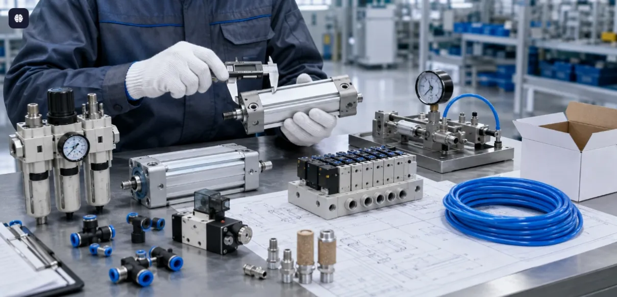
Air supply → FRL → solenoid valve → fitting → tube → flow controller
The smallest flow restriction in this chain can limit the performance of the entire pneumatic circuit.
Conclusion
Choosing the correct tube size for pneumatic fittings requires more than simply matching a tube to a fitting.
A reliable pneumatic system should consider:
Tube diameter + airflow + pressure + tubing length + operating speed + fitting flow + valve capacity
For small, low-flow applications, smaller tubing can provide a compact and economical solution. For larger cylinders, longer tubing runs, and high-speed automation equipment, a larger internal diameter may be necessary to minimize pressure drop and provide sufficient airflow.
Most importantly, always match the tube outside diameter to the pneumatic fitting specification and verify both the tube size and thread type before purchasing.
For machine builders, automation engineers, distributors, and pneumatic component buyers, selecting the correct combination of tubing and fittings can improve system response, reduce pressure losses, prevent leakage, and increase overall pneumatic system reliability.


Read next

Aug 14, 2026pneumatic fittings

How to Choose the Correct Tube Size for Pneumatic Fittings

Air supply → FRL → solenoid valve → fitting → tube → flow controller

83e82658-8bfc-4390-aa06-14806a4fffe8

How to Choose the Correct Tube Size for Pneumatic Fittings

Choosing the correct tube size for pneumatic fittings is an important part of designing an efficient and reliable compressed air system. A tube that is too small can restrict airflow and cause pressure loss, while an unnecessarily large tube may increase cost and take up more installation space.
For automation equipment, packaging machines, assembly lines, and other pneumatic systems, tube size should be selected according to airflow requirements, working pressure, tubing length, cylinder size, fitting size, and operating speed.
This guide explains how to choose the correct pneumatic tube size and avoid some of the most common selection mistakes.
1. Understanding Pneumatic Tube Sizes
Pneumatic tubing is normally specified by its outside diameter (OD).
Common metric tube sizes include:
Tube Outside Diameter
Typical Application
4 mm
Small pneumatic devices and compact equipment
6 mm
Small cylinders and general automation
8 mm
Medium-size cylinders and machinery
10 mm
Higher airflow pneumatic systems
12 mm
Large cylinders and industrial equipment
14 mm
High-flow applications
16 mm
Large pneumatic systems and main air lines
For example, a pneumatic fitting marked PC8-02 commonly indicates a straight push-in fitting designed for an 8 mm OD tube, with the other part of the code referring to the threaded connection according to the manufacturer's coding system.
Always check the supplier's dimensional specifications because model codes and thread designations can vary.
2. Why Pneumatic Tube Size Matters
Tube diameter directly affects how easily compressed air can move through a pneumatic system.
If the tube is too small, the system may experience:
  • Excessive pressure drop
  • Restricted airflow
  • Slow cylinder movement
  • Longer machine cycle times
  • Reduced cylinder performance
  • Higher energy consumption
A larger tube provides more flow capacity, but bigger is not always better.
Oversized tubing can:
  • Increase material cost
  • Require larger fittings
  • Occupy more installation space
  • Increase the volume of compressed air that must be filled and exhausted
The goal is therefore not to choose the largest tube possible, but to select the smallest practical tube that can provide the required airflow with acceptable pressure loss.
3. Match the Tube Size to the Pneumatic Fitting
One of the first things to check is whether the tube outside diameter matches the fitting.
For push-in pneumatic fittings, the tube is inserted directly into the release sleeve and sealing mechanism.
For example:
Fitting Tube Size
Recommended Tube OD
4 mm
4 mm
6 mm
6 mm
8 mm
8 mm
10 mm
10 mm
12 mm
12 mm
16 mm
16 mm
Never try to insert a tube with a different outside diameter into a push-in fitting.
Even a small dimensional mismatch may cause:
  • Air leakage
  • Poor tube retention
  • Seal damage
  • Tube disconnection
  • Unstable pneumatic performance
The tubing should also have suitable dimensional tolerance and surface quality for push-to-connect fittings.
4. Consider the Required Airflow
Airflow requirement is one of the most important factors when selecting pneumatic tubing.
A small pneumatic cylinder operating slowly may require relatively little compressed air.
A large cylinder operating at high speed requires considerably more airflow.
For example, compare:
Application A
  • Small cylinder
  • Short stroke
  • Low operating frequency
  • Short tubing
A 4 mm or 6 mm tube may be sufficient.
Application B
  • Large-bore cylinder
  • Long stroke
  • High operating frequency
  • Fast extension and retraction
An 8 mm, 10 mm, 12 mm, or larger tube may be necessary depending on the calculated flow requirement.
Therefore, tube diameter should not be selected based only on the cylinder's port thread.
5. Consider the Length of the Tube
Tube length is another factor that is sometimes overlooked.
As compressed air travels through tubing, friction causes pressure loss.
In general:
Longer tube + smaller diameter = greater pressure drop
For example, a 6 mm tube may perform well over a short distance between a solenoid valve and a small cylinder.
However, if compressed air needs to travel a much longer distance, increasing the tube diameter may help reduce pressure loss.
Whenever possible, locate pneumatic control valves close to the actuator.
This can:
  • Shorten tubing
  • Reduce pressure losses
  • Improve cylinder response
  • Reduce compressed air volume
  • Improve machine cycle time
6. Check the Inner Diameter, Not Only the Outer Diameter
Pneumatic fittings are normally selected according to the outside diameter of the tube, but airflow depends strongly on the inside diameter.
Two tubes can have the same outside diameter but different wall thicknesses.
For example:
8 mm OD tubing
does not automatically mean that every 8 mm tube provides exactly the same internal flow area.
A thicker wall means a smaller inner diameter.
Therefore, for applications where airflow is critical, engineers should check:
  • Tube OD
  • Tube ID
  • Wall thickness
  • Maximum working pressure
  • Minimum bend radius
  • Tube material
7. Metric vs Inch Pneumatic Tubing
Another common mistake is mixing metric and inch tubing.
Common metric tubing includes:
  • 4 mm
  • 6 mm
  • 8 mm
  • 10 mm
  • 12 mm
  • 16 mm
Common inch tubing includes:
  • 1/8"
  • 1/4"
  • 5/16"
  • 3/8"
  • 1/2"
A 1/4-inch tube is approximately 6.35 mm, but it should not automatically be treated as interchangeable with a 6 mm tube.
The difference may appear small, but push-in fittings depend on precise tube dimensions for sealing and gripping.
Always use:
Metric tube → metric fitting
and
Inch tube → corresponding inch fitting
unless the fitting manufacturer specifically confirms compatibility.
8. Tube Size and Thread Size Are Different
This is particularly important when purchasing pneumatic fittings.
A pneumatic fitting has two different connection dimensions:
Tube connection
and
Thread connection
For example, a fitting might connect:
8 mm tube × 1/4" thread
The 8 mm dimension describes the tube outside diameter.
The 1/4" dimension describes the threaded port.
They should not be confused.
Pneumatic fittings may also be supplied with different thread standards, including:
  • PT
  • NPT
  • BSPT
  • BSPP / G
  • Metric threads
Before ordering, confirm both the tube OD and thread standard.
9. Do Not Select Tube Size Based Only on Thread Size
A common purchasing mistake is assuming that a certain thread size always requires a certain tube diameter.
For example, equipment with a 1/4" threaded port does not necessarily mean that an 8 mm tube must be used.
Depending on the application, fittings may be available in combinations such as:
  • 6 mm × 1/4"
  • 8 mm × 1/4"
  • 10 mm × 1/4"
The correct combination depends on the required airflow, available fitting configuration, equipment design, and manufacturer's specifications.
10. Consider Working Pressure
Tube size alone does not determine whether tubing is suitable for a pneumatic system.
The tube must also be rated for the required working pressure.
Before selecting tubing, check:
  • Normal operating pressure
  • Maximum system pressure
  • Temperature
  • Safety factor
  • Tube material
  • Manufacturer's pressure rating
Never assume that two tubes of the same outside diameter have the same pressure rating.
Wall thickness and material can significantly affect pressure capability.
11. Choose the Correct Tube Material
Tube material also affects pneumatic system performance.

PU Tubing

Polyurethane (PU) tubing is widely used in industrial automation because it is flexible and easy to route.
Typical applications include:
  • Pneumatic cylinders
  • Solenoid valves
  • Packaging machines
  • Assembly equipment
  • Robotics

Nylon Tubing

Nylon tubing generally provides good mechanical strength and is often selected for applications requiring higher pressure capability or greater rigidity.

PE Tubing

Polyethylene tubing can be suitable for certain general pneumatic applications where flexibility and cost are important.
Material selection should always consider pressure, temperature, chemicals, movement, and environmental conditions.
12. A Practical Pneumatic Tube Selection Example
Suppose an automation machine uses:
  • 50 mm bore pneumatic cylinder
  • 200 mm stroke
  • 0.6 MPa operating pressure
  • Moderate operating speed
  • Short distance between valve and cylinder
Instead of automatically selecting a 6 mm tube because it is commonly available, the engineer should evaluate the required cylinder flow rate.
If the cylinder needs to operate quickly, a larger tube and higher-flow fittings may be necessary.
The complete airflow path should be considered:
Air supply → FRL → solenoid valve → fitting → tube → flow controller
The smallest flow restriction in this chain can limit the performance of the entire pneumatic circuit.
Conclusion
Choosing the correct tube size for pneumatic fittings requires more than simply matching a tube to a fitting.
A reliable pneumatic system should consider:
Tube diameter + airflow + pressure + tubing length + operating speed + fitting flow + valve capacity
For small, low-flow applications, smaller tubing can provide a compact and economical solution. For larger cylinders, longer tubing runs, and high-speed automation equipment, a larger internal diameter may be necessary to minimize pressure drop and provide sufficient airflow.
Most importantly, always match the tube outside diameter to the pneumatic fitting specification and verify both the tube size and thread type before purchasing.
For machine builders, automation engineers, distributors, and pneumatic component buyers, selecting the correct combination of tubing and fittings can improve system response, reduce pressure losses, prevent leakage, and increase overall pneumatic system reliability.


Aug 14, 2026pneumatic fittings

How to Choose the Correct Tube Size for Pneumatic Fittings

Air supply → FRL → solenoid valve → fitting → tube → flow controller

83e82658-8bfc-4390-aa06-14806a4fffe8

How to Choose the Correct Tube Size for Pneumatic Fittings

Choosing the correct tube size for pneumatic fittings is an important part of designing an efficient and reliable compressed air system. A tube that is too small can restrict airflow and cause pressure loss, while an unnecessarily large tube may increase cost and take up more installation space.
For automation equipment, packaging machines, assembly lines, and other pneumatic systems, tube size should be selected according to airflow requirements, working pressure, tubing length, cylinder size, fitting size, and operating speed.
This guide explains how to choose the correct pneumatic tube size and avoid some of the most common selection mistakes.
1. Understanding Pneumatic Tube Sizes
Pneumatic tubing is normally specified by its outside diameter (OD).
Common metric tube sizes include:
Tube Outside Diameter
Typical Application
4 mm
Small pneumatic devices and compact equipment
6 mm
Small cylinders and general automation
8 mm
Medium-size cylinders and machinery
10 mm
Higher airflow pneumatic systems
12 mm
Large cylinders and industrial equipment
14 mm
High-flow applications
16 mm
Large pneumatic systems and main air lines
For example, a pneumatic fitting marked PC8-02 commonly indicates a straight push-in fitting designed for an 8 mm OD tube, with the other part of the code referring to the threaded connection according to the manufacturer's coding system.
Always check the supplier's dimensional specifications because model codes and thread designations can vary.
2. Why Pneumatic Tube Size Matters
Tube diameter directly affects how easily compressed air can move through a pneumatic system.
If the tube is too small, the system may experience:
  • Excessive pressure drop
  • Restricted airflow
  • Slow cylinder movement
  • Longer machine cycle times
  • Reduced cylinder performance
  • Higher energy consumption
A larger tube provides more flow capacity, but bigger is not always better.
Oversized tubing can:
  • Increase material cost
  • Require larger fittings
  • Occupy more installation space
  • Increase the volume of compressed air that must be filled and exhausted
The goal is therefore not to choose the largest tube possible, but to select the smallest practical tube that can provide the required airflow with acceptable pressure loss.
3. Match the Tube Size to the Pneumatic Fitting
One of the first things to check is whether the tube outside diameter matches the fitting.
For push-in pneumatic fittings, the tube is inserted directly into the release sleeve and sealing mechanism.
For example:
Fitting Tube Size
Recommended Tube OD
4 mm
4 mm
6 mm
6 mm
8 mm
8 mm
10 mm
10 mm
12 mm
12 mm
16 mm
16 mm
Never try to insert a tube with a different outside diameter into a push-in fitting.
Even a small dimensional mismatch may cause:
  • Air leakage
  • Poor tube retention
  • Seal damage
  • Tube disconnection
  • Unstable pneumatic performance
The tubing should also have suitable dimensional tolerance and surface quality for push-to-connect fittings.
4. Consider the Required Airflow
Airflow requirement is one of the most important factors when selecting pneumatic tubing.
A small pneumatic cylinder operating slowly may require relatively little compressed air.
A large cylinder operating at high speed requires considerably more airflow.
For example, compare:
Application A
  • Small cylinder
  • Short stroke
  • Low operating frequency
  • Short tubing
A 4 mm or 6 mm tube may be sufficient.
Application B
  • Large-bore cylinder
  • Long stroke
  • High operating frequency
  • Fast extension and retraction
An 8 mm, 10 mm, 12 mm, or larger tube may be necessary depending on the calculated flow requirement.
Therefore, tube diameter should not be selected based only on the cylinder's port thread.
5. Consider the Length of the Tube
Tube length is another factor that is sometimes overlooked.
As compressed air travels through tubing, friction causes pressure loss.
In general:
Longer tube + smaller diameter = greater pressure drop
For example, a 6 mm tube may perform well over a short distance between a solenoid valve and a small cylinder.
However, if compressed air needs to travel a much longer distance, increasing the tube diameter may help reduce pressure loss.
Whenever possible, locate pneumatic control valves close to the actuator.
This can:
  • Shorten tubing
  • Reduce pressure losses
  • Improve cylinder response
  • Reduce compressed air volume
  • Improve machine cycle time
6. Check the Inner Diameter, Not Only the Outer Diameter
Pneumatic fittings are normally selected according to the outside diameter of the tube, but airflow depends strongly on the inside diameter.
Two tubes can have the same outside diameter but different wall thicknesses.
For example:
8 mm OD tubing
does not automatically mean that every 8 mm tube provides exactly the same internal flow area.
A thicker wall means a smaller inner diameter.
Therefore, for applications where airflow is critical, engineers should check:
  • Tube OD
  • Tube ID
  • Wall thickness
  • Maximum working pressure
  • Minimum bend radius
  • Tube material
7. Metric vs Inch Pneumatic Tubing
Another common mistake is mixing metric and inch tubing.
Common metric tubing includes:
  • 4 mm
  • 6 mm
  • 8 mm
  • 10 mm
  • 12 mm
  • 16 mm
Common inch tubing includes:
  • 1/8"
  • 1/4"
  • 5/16"
  • 3/8"
  • 1/2"
A 1/4-inch tube is approximately 6.35 mm, but it should not automatically be treated as interchangeable with a 6 mm tube.
The difference may appear small, but push-in fittings depend on precise tube dimensions for sealing and gripping.
Always use:
Metric tube → metric fitting
and
Inch tube → corresponding inch fitting
unless the fitting manufacturer specifically confirms compatibility.
8. Tube Size and Thread Size Are Different
This is particularly important when purchasing pneumatic fittings.
A pneumatic fitting has two different connection dimensions:
Tube connection
and
Thread connection
For example, a fitting might connect:
8 mm tube × 1/4" thread
The 8 mm dimension describes the tube outside diameter.
The 1/4" dimension describes the threaded port.
They should not be confused.
Pneumatic fittings may also be supplied with different thread standards, including:
  • PT
  • NPT
  • BSPT
  • BSPP / G
  • Metric threads
Before ordering, confirm both the tube OD and thread standard.
9. Do Not Select Tube Size Based Only on Thread Size
A common purchasing mistake is assuming that a certain thread size always requires a certain tube diameter.
For example, equipment with a 1/4" threaded port does not necessarily mean that an 8 mm tube must be used.
Depending on the application, fittings may be available in combinations such as:
  • 6 mm × 1/4"
  • 8 mm × 1/4"
  • 10 mm × 1/4"
The correct combination depends on the required airflow, available fitting configuration, equipment design, and manufacturer's specifications.
10. Consider Working Pressure
Tube size alone does not determine whether tubing is suitable for a pneumatic system.
The tube must also be rated for the required working pressure.
Before selecting tubing, check:
  • Normal operating pressure
  • Maximum system pressure
  • Temperature
  • Safety factor
  • Tube material
  • Manufacturer's pressure rating
Never assume that two tubes of the same outside diameter have the same pressure rating.
Wall thickness and material can significantly affect pressure capability.
11. Choose the Correct Tube Material
Tube material also affects pneumatic system performance.

PU Tubing

Polyurethane (PU) tubing is widely used in industrial automation because it is flexible and easy to route.
Typical applications include:
  • Pneumatic cylinders
  • Solenoid valves
  • Packaging machines
  • Assembly equipment
  • Robotics

Nylon Tubing

Nylon tubing generally provides good mechanical strength and is often selected for applications requiring higher pressure capability or greater rigidity.

PE Tubing

Polyethylene tubing can be suitable for certain general pneumatic applications where flexibility and cost are important.
Material selection should always consider pressure, temperature, chemicals, movement, and environmental conditions.
12. A Practical Pneumatic Tube Selection Example
Suppose an automation machine uses:
  • 50 mm bore pneumatic cylinder
  • 200 mm stroke
  • 0.6 MPa operating pressure
  • Moderate operating speed
  • Short distance between valve and cylinder
Instead of automatically selecting a 6 mm tube because it is commonly available, the engineer should evaluate the required cylinder flow rate.
If the cylinder needs to operate quickly, a larger tube and higher-flow fittings may be necessary.
The complete airflow path should be considered:
Air supply → FRL → solenoid valve → fitting → tube → flow controller
The smallest flow restriction in this chain can limit the performance of the entire pneumatic circuit.
Conclusion
Choosing the correct tube size for pneumatic fittings requires more than simply matching a tube to a fitting.
A reliable pneumatic system should consider:
Tube diameter + airflow + pressure + tubing length + operating speed + fitting flow + valve capacity
For small, low-flow applications, smaller tubing can provide a compact and economical solution. For larger cylinders, longer tubing runs, and high-speed automation equipment, a larger internal diameter may be necessary to minimize pressure drop and provide sufficient airflow.
Most importantly, always match the tube outside diameter to the pneumatic fitting specification and verify both the tube size and thread type before purchasing.
For machine builders, automation engineers, distributors, and pneumatic component buyers, selecting the correct combination of tubing and fittings can improve system response, reduce pressure losses, prevent leakage, and increase overall pneumatic system reliability.


Recommended articles

Guides visitors may want next

Helpful guides, field notes, and stories for choosing with more context.